Showing posts with label homebrewing. Show all posts

Saturday, February 27, 2016

Kettle Upgrade

I've upgraded my boil kettle with a sight gauge and spigot. I went with weld-less fittings for both of these because the pot I have is aluminum and the fittings are all stainless steel. I've been told that welding stainless to aluminum in possible, but is expensive. So we go with the weld-less fittings. For those of you who enjoy watching how-to videos I have posted a Kettle Spigot Install on my YouTube channel.

The sight-gauge kit I picked up from my local home brew supply store for $26.


The Spigot I used is the Bayou Classic 800-775 Stainless Steel Brew Spigot from Amazon and a bazooka kettle screen. It was $34.47 for both. I figured since I have a Bayou Classic boil kettle it made sense to use their spigot, and it didn't hurt that it was one of the less expensive spigot kits available. Also it didn't come with any extra pieces. I wanted a Female Quick Disconnect at the end of the spigot so I didn't need the barb most of the spigots came with.

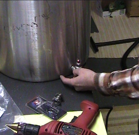
I decided to put the spigot next to the sight gauge. Keep all the controls in the same area and such. Using a step bit for my drill to make the hole. This was much easier to use then I anticipated.

The bulk that came with the spigot included 2 high temperature teflon washers and two nuts with a washer grove on one side. The double threaded fitting is put through the hole with the washer/nut combination on each side. Make sure to tighten these all the way. The washer is what creates the water tight seal here so it has to be partially compressed against the side of the kettle, or it won't seal properly. You can see the washer nested inside the groove of the nut below.


With the bulkhead in place, I put 7 wraps of teflon tape around the threads to ensure a water tight seal with the spigot. Then attache the spigot. I used a wrench on the inside to hold the bulkhead in place while tightening the spigot.


The female quick disconnect (QD) is added the same way the spigot was added to the bulkhead. 7 wraps of teflon around the threads of the QD fitting, then thread it into the spigots threaded port. Tighten with two wrenches, one on the spigot, the other on the QD.

Now I won't have to rely on a siphon to rack the wort to the fermentor, I can use gravity from the port, or I can use the pump. Either way it will be a lot faster through a half inch port then through a quarter inch tube.

Until I get the sight gauge marked off it 1/2 gallon increments I can still use my notched stir paddle to determine volume. Seems like a waste of 14 gallons of water to just pour it in, then dump it. Perhaps I'll do the marking a couple days before brew day and save the water to use on brew day. I like that idea.

Sláinte!

Tuesday, January 12, 2016

RIMS Control Unit

Last year was not the best year for me. And my brewing, or lack there of, was affected by that. However, after my short absence from brewing, I'm getting back to it. First thing I want to do now is get the RIMS unit operational. So I finally wired up the RIMS control unit. For those of you unfamiliar with the term, RIMS stands for Recirculating Infusion Mash System. It's a method for maintaining a stable mash temperature by circulating the wort past a heating element and thermometer that will keep it at the desired temperature.


First let's start with the standard disclaimer. I am not a licensed electrician. Wiring anything that uses electricity incorrectly can result in shock, fire, and possibly death. So with that in mind I proceeded to make a wiring diagram first. A friend who had wired many circuits gave me some tips on the first diagram I made and I was able to update it to the final diagram that I used, shown here for illustration purposes only.

The idea of the control unit is that main power is controlled with a switch as is power for the recirculating pump and the heating element. If the pump is turned off, the heating element is not allowed to be turned on. So the heating element switch needs to only get power if the pump switch is on. And the element itself only powered if the PID calls for power and the switch is on.

First step was to cut the holes in the cover of the project box I had. measuring out the sizes of the holes was a pain. The only controller I had that told me what size hole it needed was the PID temperature controller. The others I measured, marked and then tried to cut in the lines. My main power inlet and switch ended up with a hole that is a little large. I haven't figured out how to adjust for that yet. The other items I managed to make the holes the right size. My recommendation is to make the holes smaller than you think and then use rasp and file to enlarge them as needed to fit.

I was going to use connectors on my wires since all my items have posts or screws, however the post connectors I bought are too large. So instead of having to wait to get more I decided soldering would be the way to go. I watched a couple videos for soldering switches to refresh my memory on how to do that and then started cutting and adding my wires.


The wiring may not look super tidy, but it follows the diagram as far as the components are concerned. Using my Ohm-meter I confirmed that the 'hot' only passes power along the switches as desired. Note that the empty space on the cover of the control box is due to the Solid State Relay being used to control the power to the heating element outlet.

There is room around the heat sink so I can add a fan it needed. I'm going to run it a couple times first to see if I need the extra cooling of a fan or not.

I am hoping to do a 'wet test' in the near future to confirm the temperature controller is operating correctly. But before I do that I do need to hook up a power supply cord to the heating element of the main RIMS unit.

Sláinte!